
Views: 0 Author: Site Editor Publish Time: 2026-08-24 Origin: Site


A single incorrectly sized hydraulic connection leads to catastrophic system failure, severe safety hazards, and massive equipment downtime. Identifying replacement components gets complicated fast when original factory markings wear off. You face visual similarities between incompatible thread standards across machinery from varying international origins. Guessing thread pitches on a dirty excavator in the field is not an option when dealing with high-pressure fluid power systems.
This guide provides a technical framework for accurately measuring, identifying, and selecting the exact replacement components you need. We apply standardized measurement protocols to help you restore system integrity, prevent dangerous leaks, and maintain operational safety. You will learn how to decode thread pitches, use precision diagnostic tools, and navigate the global standards governing modern fluid power connections.
Dash Sizes Dictate Standards: Industry-standard hydraulic sizing relies on the "dash size" system, which measures in 1/16-inch increments, rather than direct fractional measurements.
Visual Identification is Insufficient: Accurate replacement requires precision tools—specifically digital calipers, thread pitch gauges, and seat angle gauges—to differentiate between metric, British, and American standards.
Thread Type Determines Seal: Selecting the correct fitting requires matching not just the thread size, but the sealing mechanism (e.g., O-ring face seal, tapered thread, or mechanical flare).
The STAMPED Framework is Non-Negotiable: Replacement fittings must align with Size, Temperature, Application, Material, Pressure, Ends, and Delivery requirements to ensure long-term reliability.
Attachment Method Matters: Choosing between permanent crimped fittings and field-attachable (reusable) fittings depends on the system's pressure rating and the availability of crimping equipment.
A successful replacement must achieve zero leaks, sustain maximum dynamic pressure ratings, resist system vibration, and maintain optimal fluid flow. Fluid power systems operate under extreme stress. Every connection point represents a potential vulnerability. When you install the correct component, the machine operates at full capacity, transferring power efficiently without generating excess heat or turbulence in the lines.
The physical and financial consequences of incorrect sizing hit hard. A mismatched thread can cause a blowout under high pressure. This leads to immediate environmental contamination and expensive cleanup efforts. High-pressure fluid injection injuries pose a severe risk to operators and technicians. Even minor sizing discrepancies create internal flow restrictions. These restrictions cause pressure drops, which accelerate pump wear and degrade overall machine performance over time. You end up replacing expensive pumps simply because a cheap connector restricted the flow.
Establishing an evaluation baseline requires identifying the host machine's country of origin. Equipment origin heavily influences the baseline thread standard. European machinery typically favors hydraulic hose fittings utilizing metric or British Standard Pipe (BSP) threads. Conversely, American-manufactured equipment predominantly utilizes Joint Industry Council (JIC) flares or O-Ring Face Seal (ORFS) connections. Knowing the equipment source narrows down the potential thread families before you even pick up a measurement tool.
Equipment Origin | Common Thread Standards | Typical Sealing Mechanism |
|---|---|---|
North America | JIC, ORFS, NPT, SAE | 37° Flare, O-Ring Face, Tapered Thread |
Europe (Germany, Italy) | DIN Metric, BSPP | 24° Cone, 60° Cone, Bonded Seal |
United Kingdom | BSPP, BSPT | 60° Cone, Tapered Thread |
Japan | JIS, Komatsu Metric | 30° Flare, 60° Cone |
By checking the manufacturer plate on the equipment, you immediately eliminate dozens of incorrect thread possibilities. A Caterpillar excavator will almost certainly use American standards, while a Liebherr crane will rely heavily on DIN metric connections.
Visual inspection alone cannot reliably differentiate between a 37-degree and a 45-degree flare. You cannot distinguish between threads that differ by a single thread per inch just by looking at them. Precision diagnostic tools are mandatory for accurate component identification in the field.
Digital calipers are your primary instrument for determining thread diameter. You must measure the Outside Diameter (OD) of male threads and the Inside Diameter (ID) of female threads. Accurate readings should be taken to the nearest thousandth of an inch or hundredth of a millimeter. Wipe all grease and debris from the threads before measuring to ensure the caliper jaws seat properly against the metal.
Thread pitch gauges are equally critical. These serrated metal templates measure threads per inch (TPI) for Imperial connections or the exact distance between thread crests in millimeters for metric variants. Seat angle gauges verify the sealing cone angle. Matching the exact angle ensures the mechanical seal seats flush, preventing fluid bypass under pressure.
Follow this strict four-step measurement workflow to guarantee accurate identification:
Identify Gender and Shape: Determine if the component is male (threads on the outside) or female (threads on the inside). Note the physical configuration, such as a straight connector, 45-degree elbow, 90-degree elbow, tee, or cross.
Measure Thread OD/ID: Keep the calipers perfectly perpendicular to the threads. Measure the OD on male components at the widest point. Measure the ID on female components at the narrowest point. Take three measurements and average them if the component appears slightly deformed.
Determine Thread Pitch: Press various blades of the pitch gauge into the threads until you find a perfect match. Light should not pass between the gauge teeth and the component threads.
Measure the Seat Angle: Insert the angle gauge into the sealing surface. Confirm whether the mechanical fit relies on a 24-degree, 30-degree, 37-degree, 45-degree, or 60-degree angle.
Thread Standard | Measurement Method | Common Pitch Values |
|---|---|---|
NPT / NPTF | Threads Per Inch (TPI) | 27, 18, 14, 11.5 |
JIC / SAE | Threads Per Inch (TPI) | 24, 20, 18, 16, 14, 12 |
BSP (BSPP/BSPT) | Threads Per Inch (TPI) | 28, 19, 14, 11 |
Metric (DIN) | Distance between crests (mm) | 1.0, 1.5, 2.0 |
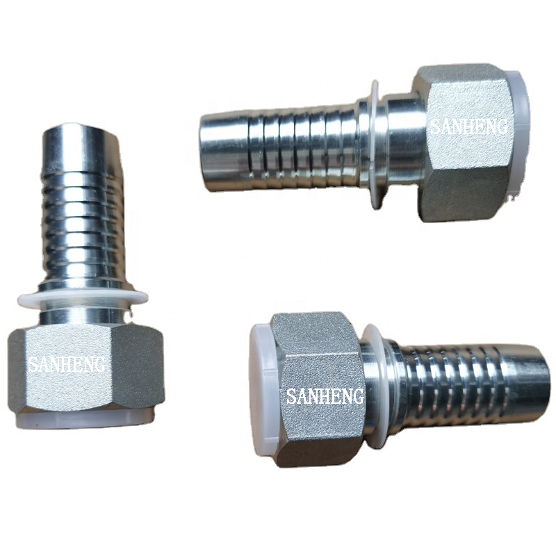
The fluid power industry relies universally on the dash size system to standardize component dimensions. Instead of using complex fractions, the dash system measures components in 1/16-inch increments. The numerator of the fraction becomes the dash number. For example, a -4 size equates to 4/16, which simplifies to 1/4 inch. A -8 size equates to 8/16, or 1/2 inch. This standardized shorthand eliminates confusion across different manufacturing sectors and simplifies ordering.
Understanding the distinction between hose measurements and tube measurements prevents major installation errors. Flexible hoses are always measured by their Inside Diameter (ID). This dictates the fluid volume and flow velocity the line can handle. If you need to move 20 gallons per minute, you size the hose ID accordingly. Conversely, rigid metal tubes and their corresponding connection points are measured by their Outside Diameter (OD). This accounts for varying wall thicknesses required for different pressure ratings.
The following table maps common dash sizes to their fractional and decimal equivalents to assist in rapid field identification.
Dash Size | Fractional Equivalent (Inches) | Decimal Equivalent (Inches) | Millimeter Equivalent (Approx) |
|---|---|---|---|
-2 | 1/8" | 0.125 | 3.2 mm |
-4 | 1/4" | 0.250 | 6.4 mm |
-6 | 3/8" | 0.375 | 9.5 mm |
-8 | 1/2" | 0.500 | 12.7 mm |
-10 | 5/8" | 0.625 | 15.9 mm |
-12 | 3/4" | 0.750 | 19.0 mm |
-16 | 1" | 1.000 | 25.4 mm |
-20 | 1×1/4" | 1.250 | 31.8 mm |
-24 | 1×1/2" | 1.500 | 38.1 mm |
-32 | 2" | 2.000 | 50.8 mm |
Navigating the various international standards requires understanding the specific sealing mechanisms and thread profiles unique to each region. Selecting the wrong category compromises system integrity and guarantees a leak.
National Pipe Tapered threads are traditional American connections. They rely on thread deformation to create a seal. As the male and female threads are drawn together, the tapered profiles wedge tightly against each other. Standard NPT requires Teflon tape or liquid thread sealant to fill microscopic gaps and prevent leaks. The NPTF (Dryseal) variant features a slightly modified crest and root, allowing for a mechanical seal without additional compounds. However, NPT hydraulic hose fittings are generally not recommended for high-pressure or high-vibration environments due to their tendency to loosen and leak over time. They are mostly found on older equipment or low-pressure return lines.
British Standard Pipe connections dominate European and Asian machinery. They are divided into two main categories: BSPP (Parallel) and BSPT (Tapered). BSPP connections do not seal on the threads. Instead, they utilize a 60-degree cone seat or a bonded seal ring at the base of the thread. BSPT connections seal via thread interference similar to NPT. It is critical to note the visual differences to prevent cross-threading. BSP threads feature a 55-degree thread angle with rounded peaks and valleys, whereas NPT uses a 60-degree angle with flattened peaks. Mixing these will destroy the threads. Utilizing correct BSP hydraulic hose fittings ensures compatibility with imported heavy equipment like JCB or Volvo construction machinery.
Metric connections are highly standardized under the Deutsches Institut für Normung (DIN). The most common variant is the DIN 2353 standard, which utilizes a 24-degree inner cone. These are further categorized into Light (L) and Heavy (S) series. The Light series handles standard industrial pressures, while the Heavy series features thicker walls for extreme high-pressure applications. Japanese industrial equipment often utilizes Komatsu or JIS metric standards, which feature a unique 30-degree flare requirement. Identifying the exact series is crucial when sourcing metric hydraulic hose fittings to ensure the pressure rating matches the system demands.
Joint Industry Council (JIC) connections utilize a 37-degree flare seating surface. They dominate high-pressure American applications due to their excellent mechanical sealing properties and ease of assembly. They are frequently confused with SAE 45-degree flare connections, which are typically reserved for lower-pressure automotive or refrigeration systems. O-Ring Face Seal (ORFS) connections represent the highest standard for leak prevention. They feature a flat face with an embedded O-ring that compresses against a flat female surface. ORFS components are superior in eliminating leaks in high-vibration systems like forestry mulchers or rock crushers.
Permanent crimped connections are mandatory for modern high-pressure applications. They require specialized crimping machines to compress the metal collar permanently into the hose cover, creating a bond that withstands extreme burst pressures. Field-attachable, or reusable, connections offer utility for emergency repairs on low-to-medium pressure lines. They can be assembled using standard hand tools, allowing technicians to restore basic functionality in remote locations without access to crimping equipment.
The STAMPED framework provides a comprehensive checklist for selecting replacement components. Adhering to these criteria ensures the new part matches the exact operational parameters of the original system.
Size: The inner diameter of the replacement component must match the hose ID. Undersized components restrict fluid flow, which increases fluid velocity. This excess velocity generates heat, causes pressure drops, and severely reduces the lifespan of system pumps and valves. Always verify the dash size matches the flow requirements.
Temperature: Ambient operating temperatures and internal fluid temperatures dictate the required O-ring materials. Standard Nitrile (Buna-N) seals perform well in general applications. High-temperature environments or synthetic fluids require Viton or specialized elastomers to prevent seal degradation, hardening, and subsequent leaks.
Application: Consider where the equipment operates. A machine working in a corrosive salt-mine environment requires different component protection than a machine operating in a clean indoor manufacturing facility. The application dictates the physical shape needed, such as using 90-degree elbows to route lines safely away from moving pinch points.
Material: Carbon steel remains the standard industry choice. It is highly cost-effective and handles extreme pressures, though it is susceptible to exterior corrosion if the protective plating wears off. Stainless steel offers exceptional corrosion resistance and temperature tolerance, making it ideal for marine or chemical environments. Brass is suitable only for low-pressure applications and specific fluid compatibility; it lacks the structural integrity required for high-pressure fluid power.
Pressure: The dynamic pressure rating of the replacement component must meet or exceed the system's maximum operating pressure. Industry standards require a 4:1 safety burst ratio. A component rated for 3,000 PSI working pressure is engineered to withstand spikes up to 12,000 PSI before catastrophic failure. Never downgrade the pressure rating of a replacement part.
Ends: This refers to the specific thread type and sealing mechanism. You must correctly identify if the end is NPT, JIC, ORFS, or DIN Metric. Matching the ends perfectly is the only way to guarantee a leak-free mechanical seal.
Delivery: Factor in the availability and lead time of the components. In emergency breakdown situations, you need to know which suppliers stock the exact STAMPED-compliant parts to minimize equipment downtime.
The greatest risk during replacement is forcing incompatible threads together. Threading an NPT male into a BSPT female may initially feel secure because the thread pitches are similar. The differing thread angles (60 degrees vs. 55 degrees) prevent a true seal. This creates a false sense of security. Under high pressure, the connection will inevitably blow out, causing severe equipment damage and posing a lethal hazard to bystanders.
Torque application requires strict adherence to manufacturer specifications. Over-torquing causes thread galling, distorts the sealing cone, and can crack female cast iron ports. Under-torquing allows vibration to loosen the connection, leading to O-ring extrusion and weeping leaks. Technicians should utilize the Flats From Wrench Resistance (FFWR) method. This involves tightening the nut finger-tight until it bottoms out, then using a wrench to turn it a specific number of flats (hex sides) as dictated by the component size and standard.
Dash Size | JIC 37° Flare (FFWR) | ORFS (FFWR) |
|---|---|---|
-4 (1/4") | 2 Flats | 1/2 to 3/4 Flat |
-6 (3/8") | 1.5 Flats | 1/2 to 3/4 Flat |
-8 (1/2") | 1.5 Flats | 1/2 to 3/4 Flat |
-12 (3/4") | 1.25 Flats | 1/3 to 1/2 Flat |
-16 (1") | 1 Flat | 1/3 to 1/2 Flat |
Routing and bend radius directly impact hose longevity. The choice of component shape—whether straight, 45-degree, or 90-degree—must facilitate a natural hose path. Proper routing prevents the hose from twisting during installation. Twisting reduces the hose's pressure capacity by up to 20 percent. Utilizing angled connectors minimizes the overall system pressure drop and prevents the hose from exceeding its minimum bend radius.
Document the exact thread OD, ID, pitch, and seat angle using precision calipers and gauges before ordering parts.
Cross-reference your measurements with a standardized dash size chart to confirm the exact component dimensions.
Verify the dynamic pressure rating of the replacement part meets or exceeds your system's maximum operating pressure.
Source your replacement components from certified industrial suppliers to guarantee material integrity and safety compliance.
A: The dash size system measures components in 1/16-inch increments. To convert, place the dash number over 16 and reduce the fraction. A -6 dash size equals 6/16, which reduces to 3/8 inch. A -12 dash size equals 12/16, which reduces to 3/4 inch.
A: NPT uses a 60-degree thread angle with flattened peaks and valleys. BSP uses a 55-degree thread angle with rounded peaks and valleys. They are not interchangeable. Forcing them together will damage the threads and cause high-pressure blowouts.
A: Yes. The hose is measured by its internal diameter (ID) and accepts different end connections as long as the crimp collar and hose tail match the hose ID and pressure rating. The thread standard only dictates how it connects to the machine port.
A: Use a specialized seat angle gauge. Insert the gauge into the sealing cone of the component. Check for daylight between the gauge and the sealing surface. If it sits perfectly flush, the angle matches the gauge.
A: Leaks occur due to mismatched thread standards, missing O-rings, or incorrect torque application. Over-torquing cracks the flare or extrudes the O-ring. Under-torquing fails to compress the mechanical seal. Verify the thread pitch and re-check the torque specifications.
A: No. JIC connections use a 37-degree flare angle, whereas SAE connections use a 45-degree flare angle. Connecting them together prevents a proper mechanical seal, resulting in severe leaks under pressure.


