
Views: 0 Author: Site Editor Publish Time: 2026-08-03 Origin: Site


Mismatched threads or incorrect seat angles in high-pressure fluid systems cause leaks, equipment downtime, and safety hazards. When a line blows on heavy machinery, production stops immediately. Maintenance teams struggle to visually identify thread types across mixed fleets. Documentation goes missing or becomes illegible after years in the dirt. You often deal with Japanese excavators, German presses, and American tractors in the same facility. Each uses completely different fluid connection standards.
Visual estimation fails when systems operate at 5,000 PSI. Technicians need a systematic, tool-based method to measure and verify specifications. Using the right tools turns identifying hydraulic fittings into a fast, repeatable process. This workflow lets you determine exact specs in under 90 seconds. You get secure connections, stop the leaks, and get the machine running again.
Accurate identification requires three specific tools: a precision caliper (ID/OD), a thread pitch gauge, and a seat angle gauge.
The measurement process must follow a strict sequence: identifying shape/type, determining thread taper, measuring diameter, calculating pitch, verifying seat angle, and measuring total length.
Distinguishing between regional and international standards (e.g., NPT, JIC, BSP, DIN) is critical for procurement and system compliance.
Translating physical measurements into exact part specifications and industry dash sizes mitigates the risk of cross-threading and pressure blowouts during implementation.
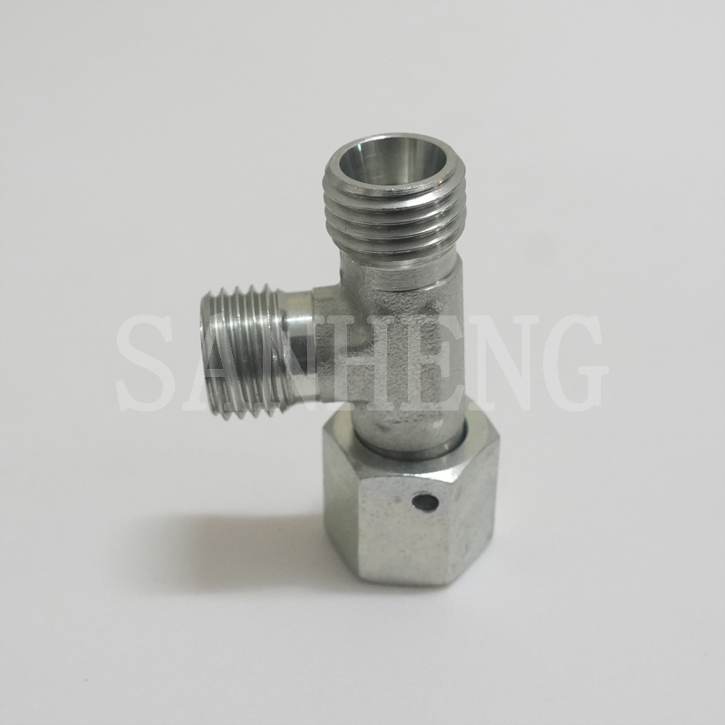
A successful replacement part must meet strict criteria. It needs to hold the rated system pressure, engage the threads perfectly, and fit within the physical space of the machine. Achieving this requires matching every physical characteristic of the original part. When you replace a blown component, the new part must integrate into the existing circuit without putting stress on the hoses or the pump.
Forcing incompatible threads together destroys equipment. Mixing a National Pipe Taper (NPT) fitting with a British Standard Pipe Taper (BSPT) port feels tight at first. However, NPT threads use a 60-degree angle, while BSPT threads use a 55-degree angle. Wrenching them together crushes the metal crests against the roots. This destroys the threads and ruins the seal. Under high operational loads, fluid bypasses the deformed metal. You get a sudden pressure loss or a dangerous blowout.
Visual estimation is an unacceptable practice in industrial fluid power. You cannot see the difference between a 37-degree flare and a 45-degree flare with the naked eye. Installing the wrong one guarantees a leak. Implementing a strict measurement protocol protects your personnel and your machinery from preventable failures.
You cannot accurately identify fluid power components with a tape measure. The tight tolerances required for high-pressure sealing demand specialized instruments. Equipping your maintenance team with the correct tools is the first step toward eliminating connection failures.
Digital calipers provide the exact outer diameter (OD) and inner diameter (ID) readings you need. Before measuring, wipe the jaws clean. Close them completely and hit the zero button. For male threads, open the lower jaws. Place them flat across the crests of the threads. Do not tilt the caliper, as tilting gives a false, oversized reading. Roll the caliper slightly to find the absolute widest point. Record this number in both inches and millimeters. For female threads, use the upper jaws. Insert them into the port. Open them until they contact the thread roots. Wiggle the caliper slightly to ensure you are seated in the deepest part of the root.
A thread pitch gauge looks like a pocketknife with dozens of serrated blades. Each blade represents a specific thread count or metric distance. Start by guessing the pitch visually and pull out a blade that looks close. Press the serrated edge directly into the threads of your fitting. Hold the fitting up to a bright light source. Look closely at the mating surface. If you see light shining through the gaps between the gauge and the threads, the pitch is wrong. Fold that blade away and try the next size up or down. You want a perfect, flush fit where the gauge locks into the threads with zero daylight visible.
In many high-pressure applications, the threads merely hold the connection together. The machined angle inside the fitting creates the actual fluid seal. You must measure this sealing surface angle accurately. Common angles include 37 degrees, 45 degrees, and 24 degrees. Insert the gauge into the fitting and check for light gaps. This ensures you identify the primary sealing mechanism correctly before ordering a replacement.
Follow this exact sequence every time you pull a part off a machine. Skipping steps leads to ordering the wrong standard.
Clean and Inspect: Thoroughly clean the component using brake cleaner and a wire brush. Wipe away accumulated dirt and grease. Look for manufacturer stamps, thread series identifiers, or dash sizes etched directly into the hex nut. Finding a marking like "-08" or "JIC 37" gives you a baseline for verification.
Identify the Configuration: Look at the overall geometry. Is it a straight connector? Is it a 90-degree elbow? Or are you dealing with hydraulic tee fittings used to split flow across multiple circuits? Next, identify the sealing mechanism. Does it use an O-ring, a metal-to-metal seat, or mated tapered threads?
Check for Taper: Establish whether the threads run parallel to each other or taper down like a cone. Use your calipers to measure the outer diameter of the first full thread at the tip. Record this number. Measure the fourth full thread. Finally, measure the last full thread near the hex nut base. If the diameter decreases toward the end, the threads are tapered. If the diameter remains constant, they are parallel.
Measure the Diameter: Use your calipers to measure the exact OD for male threads or ID for female threads. Record your measurements in both inches and millimeters. Global specification charts mix imperial and metric designations. Having both numbers ready prevents calculation errors later.
Determine the Pitch: Press your thread pitch gauge into the threads. For North American and British standards, the gauge tells you the number of Threads Per Inch (TPI). A reading of 14 means there are 14 threads in a one-inch span. For European equipment, the gauge measures the exact distance in millimeters between consecutive thread crests.
Measure the Seat Angle: If the component uses a metal-to-metal sealing surface, insert the appropriate blade of your seat angle gauge directly into the fitting. Hold it up to the light to ensure a perfect, gap-free fit.
Measure Total Length: Use your calipers to measure the overall end-to-end length of straight connectors. This ensures the replacement part fits within the physical constraints of the machine framework. For angled components, measure the drop length from the centerline of the fitting body to the end of the threaded connection.
Once you have your measurements, you need to match them to a specific global standard. Machinery uses different standards depending on where it was manufactured.
North American machinery relies heavily on three primary standards. National Pipe Taper (NPT) seals through the deformation of tapered threads. Joint Industry Council (JIC) fittings use parallel threads and a 37-degree flared seat for high-pressure sealing. Society of Automotive Engineers (SAE) fittings look nearly identical to JIC but use a 45-degree flare. You must check the seat angle to differentiate them accurately. Mixing JIC and SAE components causes immediate leaks.
British Standard Pipe (BSP) comes in parallel (BSPP) and tapered (BSPT) variations. They use a 55-degree thread angle that differs from the American 60-degree standard. German Deutsches Institut für Normung (DIN) standards dominate European heavy machinery.
When identifying metric hydraulic fittings, look for parallel threads measured by the exact millimeter distance between crests. The 24-degree internal cone standard is universally common in DIN equipment. It is often paired with an internal O-ring to resist heavy vibration and prevent leaks under extreme pressure spikes.
Rigid steel tubing requires a different approach than flexible hoses. Bite type hydraulic fittings create a seal by driving a hardened metal ferrule directly into the outer wall of the steel tube. When measuring these connections, the tube Outer Diameter (OD) is the most critical dimension. It dictates the size of the nut and ferrule required. You must also identify the thread specifications on the fitting body. The threads pull the nut forward to compress the ferrule. If the thread pitch is wrong, the nut will not generate enough clamping force, and the tube will blow out under load.
Standard | Thread Type | Common Seat Angle | Pitch Measurement |
|---|---|---|---|
NPT | Tapered | 60° Thread Angle | Threads Per Inch (TPI) |
JIC (SAE 37°) | Parallel | 37° Flare | Threads Per Inch (TPI) |
SAE 45° | Parallel | 45° Flare | Threads Per Inch (TPI) |
BSPP | Parallel | 30° Cone | Threads Per Inch (TPI) |
BSPT | Tapered | 55° Thread Angle | Threads Per Inch (TPI) |
DIN 24° | Parallel | 24° Cone | Millimeters (mm) |
ORFS | Parallel | Flat Face (O-Ring) | Threads Per Inch (TPI) |
Field technicians make a few common mistakes when identifying parts. Knowing these risks helps you avoid destroying new components during installation.
Confusing JIC 37° and SAE 45°: To the naked eye, these flares look identical. Technicians often grab the wrong part from the bin. If you mate a JIC female to an SAE male, the angles clash. You get a single point of contact rather than a broad sealing surface. It leaks immediately upon pressurization. You must use a seat angle gauge on every flared component.
Misidentifying BSPT and NPT: Because both are tapered threads, NPT and BSPT get confused constantly. BSPT uses a 55-degree thread angle, while NPT uses a 60-degree angle. Their pitch sizes are also slightly different. Threading them together causes severe metal galling and permanent damage to the port.
Measuring Worn Threads: Measuring rusted or stripped threads presents a massive challenge. Calipers slip, and pitch gauges will not sit flush against damaged crests. When facing this issue, measure the un-worn sections of the thread near the base of the hex nut. The metal is usually preserved there. Alternatively, measure the mating port. Internal threads are often protected from physical impact and environmental degradation.
Once you gather your raw data, you must translate it into actionable procurement language. The fluid power industry relies on the "dash size" system to standardize ordering. Decoding dash sizes is straightforward. The size is based on sixteenths of an inch.
Dash Size | Fractional Equivalent | Decimal Equivalent (Inches) |
|---|---|---|
-04 | 1/4" | 0.250 |
-06 | 3/8" | 0.375 |
-08 | 1/2" | 0.500 |
-10 | 5/8" | 0.625 |
-12 | 3/4" | 0.750 |
-16 | 1" | 1.000 |
-20 | 1.1/4" | 1.250 |
-24 | 1.1/2" | 1.500 |
You must cross-reference your gathered data with standard thread identification charts. These charts act as a translation matrix. They turn raw numbers into specific standard designations. For example, converting an OD of 0.84 inches with 14 TPI into a 1/2" NPT designation. Pinpointing the exact part number ensures the replacement component matches the original equipment specifications.
Consider material selection based on the operating environment. Carbon steel is the industry standard for general applications. Stainless steel is required for highly corrosive environments or marine applications. Brass is reserved for lower-pressure applications or pneumatic systems. Selecting the correct material prevents premature degradation.
Clean all components with solvent and a wire brush before taking any measurements to reveal stamped identifiers.
Zero your digital calipers and verify the calibration against a known standard before measuring thread diameters.
Measure the first, fourth, and last full thread to confirm if the profile is tapered or parallel.
Cross-reference your OD, ID, and pitch data against a standardized thread identification chart to determine the exact dash size.
A: Both are tapered threads, but they use different geometries. NPT uses a 60-degree thread angle with flat crests and roots. BSPT uses a 55-degree thread angle with rounded crests and roots. Forcing them together causes severe metal galling and guarantees a leak under pressure.
A: You need a specialized seat angle gauge. Insert the gauge blades into the machined sealing surface of the fitting. Hold the component up to a bright light source. The correct angle blade will sit perfectly flush against the metal. If you see any daylight shining through, try a different angle blade.
A: No. Metric and imperial components feature completely different thread pitches, diameters, and sealing angles. Threading them together will strip the metal and destroy the pressure seal. You must install specific adapter fittings to safely transition between metric and imperial fluid systems.
A: Grab your digital caliper. Measure the outer diameter of the first full thread, the middle thread, and the last full thread near the hex nut. If the diameter steadily decreases toward the tip, the thread is tapered. If the measurement remains identical across all threads, it is parallel.
A: You need a precision digital caliper to measure the exact outer diameter (OD) of the steel tube. The ferrule size directly corresponds to this tube OD. You also need a thread pitch gauge to identify the thread specifications on the main fitting body that compresses the nut.
A: Place your caliper at the exact centerline of the fitting's main body. Measure from that center point straight down to the absolute end of the threaded connection on the branching port. Getting this measurement right ensures you have proper clearance for hose routing without bending the line too sharply.
A: Dash sizes represent the size of the component in sixteenths of an inch. To read them, simply place the dash number over 16 and reduce the fraction. For example, a -04 size is 4/16, which reduces to 1/4 inch. A -12 size is 12/16, which reduces to 3/4 inch.


