
Views: 0 Author: Site Editor Publish Time: 2026-08-10 Origin: Site


Incorrectly specified hydraulic connections are a leading cause of fluid leaks, catastrophic system blowouts, and unplanned operational downtime in high-pressure environments. Global manufacturing relies on a fragmented ecosystem of thread standards, including NPT, JIC, ORFS, BSP, BSPT, and DIN metric connections. Procurement teams, pipe fitters, and hydraulic engineers frequently struggle to accurately identify existing threads or specify new hydraulic fittings without risking cross-threading, incorrect seat matching, or pressure seal failures.
This guide provides comprehensive hydraulic fittings size charts, exact measurement protocols, model selection examples, and technical evaluation criteria to help you choose the correct component for your system’s pressure, vibration, and compatibility requirements. In addition to the common sizes listed in this article, Sanheng supplies more hydraulic fitting parameters for purchase, including NPT male fittings, BSP 60° cone fittings, BSPT male fittings, JIC 74° cone / SAE 37° flare fittings, ORFS male O-ring fittings, and metric bite type tube fittings. More thread combinations, dimensions, materials, pressure ratings, O-ring sizes, and customized specifications are available. If the exact model or parameter you need is not shown here, contact us(+86-18892626763、kxf@yuyaosanheng.com) with your drawing, sample photo, thread size, material requirement, and order quantity for more product details.
Measurement Precision is Non-Negotiable: Accurate identification requires a caliper for outer/inner diameter, also called O.D. and I.D., and a thread pitch gauge for threads per inch or metric pitch.
Sealing Mechanisms Dictate Application: Fittings seal via tapered threads, metal-to-metal flares, 60° cone seats, bonded seals, or O-rings. Mismatched sealing types will fail under operational pressure.
Visual Similarity is Deceptive: NPT and BSPT threads appear nearly identical but feature different thread angles and pitches, making them incompatible without correct verification.
Model Numbers Help Purchasing: Sanheng model numbers such as 1N, 1B, 1T-SP, 1J, 1F, 1C, and 1D identify different fitting series and help buyers match thread type, sealing style, tube O.D., and material.
More Parameters Are Available: The charts in this guide show common thread standards and representative sizes only. We can provide more hydraulic fitting parameters for purchase, including different thread combinations, larger sizes, wrench flats, overall lengths, O-ring sizes, carbon steel, stainless steel, brass options, and complete sets with nuts or cutting rings where applicable.
You cannot identify hydraulic threads by eye. Technicians must use calibrated tools to determine exact specifications. Guesswork leads to stripped ports and hazardous fluid injection injuries. Always clean the connection thoroughly with a wire brush and solvent before taking any measurements. Dirt, dried thread sealant, and hydraulic fluid distort tool readings and lead to incorrect part orders.
Calipers: You need a digital or dial caliper to measure diameters accurately. Measure the precise outer diameter of male threads by placing the lower caliper jaws over the widest part of the threads. Ensure the caliper sits perfectly perpendicular to the fitting body. Measure the inner diameter of female threads using the top jaws of the caliper. Insert them into the port and expand until they touch the thread crests. These measurements establish the nominal size of the connection.
Thread Pitch Gauges: This tool determines the spacing between threads. For imperial connections, it measures threads per inch. For metric connections, it measures the exact millimeter distance between thread crests. Press the gauge firmly against the threads and hold it up to a light source. If you see light between the gauge teeth and the threads, try a different pitch leaf. The correct leaf will seat perfectly into the thread valleys without any rocking motion.
Seat Angle Gauges: The sealing surface angle dictates how the connection holds pressure. Use a specialized seat angle gauge to identify the geometry. Common angles include 37°, 45°, 60°, and 24°. Insert the gauge onto the sealing cone or flare. A perfect match ensures proper male-to-female mating mechanics. Mismatched angles guarantee a leak under operational load.
Wipe the fitting completely clean of all oil, grease, thread sealant, and debris.
Use the caliper to measure the thread O.D. for male threads or I.D. for female threads and record the decimal value.
Test various leaves on the thread pitch gauge until one locks perfectly into the threads. Record the TPI or metric pitch.
Place the seat angle gauge against the sealing surface to determine the flare, cone, or face-seal geometry.
Compare your recorded measurements against standard hydraulic fitting size charts and catalog parameters to confirm the exact thread type and model.
Every hydraulic connection is defined by four specific geometric parameters. You must identify all four to specify a replacement part accurately.
Pitch: This measures the thread density. It is the distance between thread crests in metric systems. In imperial systems, it counts the total threads per inch.
Angle: This describes the geometry of the thread profile or sealing seat. For example, NPT uses a 60° thread profile, BSP uses a 55° thread profile, JIC uses a 37° flare sealing angle, and DIN metric tube fittings commonly use a 24° cone.
Diameter: This includes the nominal size and the actual measured widths. The measured O.D. rarely matches the nominal fractional name.
Form: This identifies the profile shape. Parallel threads maintain a consistent diameter from end to end. Tapered threads narrow visibly toward the tip of the fitting.
Hydraulic systems contain fluid under extreme pressure. The threads alone rarely hold this pressure. The connection relies on a specific sealing mechanism to prevent leaks. Understanding these mechanisms helps you choose the right component for the job.
Interference Fit: This method relies on tapered thread deformation. The male and female threads wedge together as you tighten them. This requires sealants like PTFE tape or liquid paste to fill microscopic gaps. There is a high risk of over-tightening, especially in cast iron or aluminum ports.
Metal-to-Metal Flare or Cone: This mechanism relies on machined angles mating under torque. The male cone or flare presses into the female cone. This creates a mechanical seal without elastomers. It performs well in high-vibration environments and handles wide temperature changes.
Elastomeric Seal: This sealing method uses an O-ring or bonded seal. An O-ring compresses between two metal surfaces and provides excellent leak resistance in high-pressure applications. The O-ring material must match the hydraulic fluid, working temperature, and operating environment.
After identifying the thread type, buyers still need to convert the measurement into an actual orderable part number. Sanheng catalog model numbers are designed to show the fitting series, thread combination, sealing structure, and size range. The part number normally starts with a product family code, followed by one or two size codes. For example, a single-size model such as 1N-04 usually means both ends use the same thread size, while a reducing model such as 1N-04-08 means the E end and F end use different thread sizes.
When reading our parameter tables, pay attention to these columns:
Part No.: The order model or catalog code.
E / F Thread: The thread specification on each end of the fitting.
D1 / D2 or Tube O.D.: Tube outside diameter for metric bite type or flared tube fittings.
A / B / L / L1: Key fitting dimensions, including thread engagement length and overall length.
S1 / S2 / S3: Wrench flat sizes used for installation.
O-ring: O-ring size for ORFS fittings.
Pressure Rating: Working pressure level for applicable metric tube fitting series.
The table below gives several practical examples from our available parameter ranges. These examples do not represent the full product range. More sizes and thread combinations are available upon request.
Example Model | Fitting Type | Main Parameters | How to Select |
|---|---|---|---|
1C-16 | Metric thread bite type tube fitting, light series | E/F: M16×1.5; Tube O.D.: 10 mm; L1: 42 mm; S1/S2/S3: 17/19/19; Pressure: 31.5 MPa | Choose this model when the system uses M16×1.5 metric threads with 10 mm tube O.D. in a light-series hydraulic line. |
1D-20 | Metric thread bite type tube fitting, heavy series | E/F: M20×1.5; Tube O.D.: 12 mm; L1: 51 mm; S1/S2/S3: 22/24/24; Pressure: 63 MPa | Choose heavy-series 1D models when the application requires higher pressure resistance than the light-series 1C fittings. |
1B-04-08 | BSP male double use for 60° seat or bonded seal | E: G1/4×19; F: G1/2×14; A: 12 mm; B: 16 mm; L: 38 mm; S1: 27 mm | Use this reducing BSP adapter when one port is G1/4 and the opposite connection needs G1/2. |
1T-08-12SP | BSPT male tapered thread fitting | E: R1/2×14; F: R3/4×14; A: 20 mm; B: 20 mm; L: 48 mm; S1: 30 mm | Choose this model when converting from R1/2 BSPT male thread to R3/4 BSPT male thread. |
1N-08-16 | NPT male tapered thread fitting | E: Z1/2×14; F: Z1×11.5; A: 19.5 mm; B: 25.5 mm; L: 56 mm; S1: 36 mm | Select this NPT adapter when a 1/2 inch NPT connection needs to transition to a 1 inch NPT connection. |
1J-08-12 | JIC male 74° cone / SAE 37° flare fitting | E: 3/4×16; F: 1.1/16×12; A: 16.7 mm; B: 21.9 mm; L: 48.5 mm; S1: 30 mm | Use this model when adapting a JIC -8 connection to a JIC -12 connection while maintaining the correct flare sealing geometry. |
1F-08 | ORFS male O-ring face seal fitting | E/F: 13/16×16; O-ring: 12.42×1.78; A/B: 12.8 mm; L: 35.4 mm; S1: 22 mm | Choose this ORFS fitting when a leak-resistant flat-face O-ring seal is required for a 13/16×16 ORFS connection. |
Material suffixes can also be selected according to the application. In many catalog series, the standard model refers to carbon steel. Add SS when stainless steel is required, or EE when brass is required. For example, 1N-04-SS indicates a stainless steel NPT adapter, while 1N-04-EE indicates a brass adapter. For metric bite type fittings, complete sets with nut and cutting ring can be ordered by adding the required set suffix, such as 1C-30RN. Please confirm the final coding with our sales team before placing an order.
NPT is one of the oldest connection standards still in use. You will find it extensively in North American industrial equipment, air compressors, and legacy hydraulic power units. The definitive traits include a 60° thread angle and a tapered thread profile. The diameter shrinks as you move toward the tip of the male end.
The sealing mechanism relies on thread deformation. The tapered design forces the threads to bind together. This metal-to-metal wedging leaves a spiral leak path at the thread crests. You must use PTFE tape or a liquid thread sealant. The sealant fills the spiral path to prevent fluid from escaping under pressure.
Clean the male threads with a degreaser and let them dry completely.
Start wrapping the tape one thread back from the tip to prevent tape shreds from entering the hydraulic system.
Wrap the tape in the direction of the threads, clockwise when looking at the tip. This prevents the tape from unspooling during installation.
Apply exactly two to three tight wraps. Excess tape will prevent the threads from engaging properly.
Tear the tape and press the loose end firmly into the threads.
Use this table to identify standard NPT hydraulic fittings based on your caliper and gauge measurements. The measured O.D. is significantly larger than the nominal pipe size.
Dash Size | Nominal Pipe Size | Threads Per Inch | Male Thread O.D. | Female Thread I.D. |
|---|---|---|---|---|
-2 | 1/8 inch | 27 | 0.41 inch | 0.38 inch |
-4 | 1/4 inch | 18 | 0.54 inch | 0.49 inch |
-6 | 3/8 inch | 18 | 0.68 inch | 0.63 inch |
-8 | 1/2 inch | 14 | 0.84 inch | 0.77 inch |
-12 | 3/4 inch | 14 | 1.05 inch | 0.98 inch |
-16 | 1 inch | 11.5 | 1.32 inch | 1.24 inch |
-20 | 1-1/4 inch | 11.5 | 1.66 inch | 1.58 inch |
-24 | 1-1/2 inch | 11.5 | 1.90 inch | 1.82 inch |
In some catalog tables, the NPT thread column may be marked with the Z designation. The selection logic is simple: match the E thread and F thread first, then verify the overall length L and wrench flat S1.
For example:1N-04
Both ends are Z1/4×18 NPT male threads. A and B are 15 mm, overall length L is 36 mm, and S1 is 17 mm. This is suitable when both ports are 1/4 inch NPT.
More NPT parameters are available, including larger sizes, reducing combinations, stainless steel versions, and brass versions. Contact us if your required NPT thread combination is not listed in the standard chart.
NPT components are widely available across North America. They are cost-effective for general-purpose fluid routing. You can use them safely in low-to-medium pressure applications. They work well for stationary equipment where vibration is minimal and plumbing lines remain permanently fixed.
However, NPT is susceptible to thread galling, especially in stainless steel systems. You cannot infinitely reassemble these connections. Each installation deforms the threads further. Eventually, the connection bottoms out before sealing. NPT fittings are also prone to cracking cast iron or aluminum ports if over-torqued by inexperienced technicians trying to stop a persistent drip.
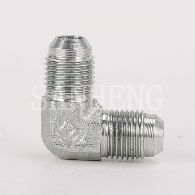
JIC connections dominate the mobile equipment sector, agricultural machinery, and heavy construction equipment. They are easily recognizable by their straight UNF threads and distinct 37° flared seating surface. Some product catalogs describe the same connection as a JIC 74° cone because 74° refers to the included cone angle, while 37° refers to the sealing angle on each side. Unlike NPT, the threads do not taper. The threads serve only to pull the components together mechanically.
The sealing mechanism relies entirely on metal-to-metal contact. The male flare presses tightly against the female cone. As you apply torque, the two angled surfaces coin together. This creates a robust seal. You do not use PTFE tape or liquid sealants on JIC connections. Applying sealants interferes with the metal-to-metal seating process and introduces contamination into the fluid stream.
This table helps you identify standard JIC hydraulic fittings. Measure the straight thread O.D. and verify the UNF thread pitch.
Dash Size | Thread Size | Tube O.D. | Male Thread O.D. | Female Thread I.D. |
|---|---|---|---|---|
-4 | 7/16×20 | 1/4 inch | 0.44 inch | 0.39 inch |
-5 | 1/2×20 | 5/16 inch | 0.50 inch | 0.45 inch |
-6 | 9/16×18 | 3/8 inch | 0.56 inch | 0.51 inch |
-8 | 3/4×16 | 1/2 inch | 0.75 inch | 0.69 inch |
-10 | 7/8×14 | 5/8 inch | 0.88 inch | 0.81 inch |
-12 | 1.1/16×12 | 3/4 inch | 1.06 inch | 0.98 inch |
-16 | 1.5/16×12 | 1 inch | 1.31 inch | 1.23 inch |
-20 | 1.5/8×12 | 1-1/4 inch | 1.63 inch | 1.54 inch |
The catalog may describe these products as JIC male 74° cone. This 74° value refers to the included cone angle and corresponds to the commonly used SAE 37° flare sealing angle on each side. When selecting JIC fittings, verify the thread size, dash size, sealing cone, and wrench flat.
For example:1J-06
Both ends use 9/16×18 thread. The overall length L is 34.2 mm and S1 is 17 mm. This is commonly selected for JIC -6 connections.
For JIC tube fittings, nuts and sleeves may need to be ordered separately depending on the tube type. If you are not sure whether your assembly requires a nut, sleeve, metric tube accessory, or inch tube accessory, send us the tube O.D. and connection photo for confirmation.
JIC offers excellent reusability compared to tapered threads. You can assemble and disassemble them multiple times without losing sealing integrity. They are reliable in high-pressure and high-vibration applications. They are also easy to adapt to metric tubing using specialized sleeves and nuts, making them versatile for field repairs.
They are vulnerable to nose collapse if over-torqued. Excessive wrenching crushes the 37° flare inward. This restricts fluid flow and ruins the seal. Creating custom tube assemblies requires precise flaring tools. Poorly prepared tube flares will leak regardless of how tight you make the nut. Mechanics must ensure the tube is cut square and deburred before flaring.
ORFS represents a modern standard for leak-resistant fluid power in heavy industry. The definitive traits include straight UNF threads and a flat machined face on the male end. This flat face contains a machined groove holding a captive O-ring. The female end features a matching flat face and straight threads.
The sealing mechanism relies entirely on elastomeric compression. As you tighten the nut, the flat face of the female component compresses the O-ring into the groove of the male component. The straight threads provide the mechanical holding power. The O-ring creates a high-performance leak barrier against high-pressure fluid. This design prevents the O-ring from extruding under extreme pressure spikes when correctly specified.
Use this chart to verify ORFS dimensions. Notice that the thread sizes differ slightly from JIC for the same tube O.D.
Dash Size | Thread Size | Tube O.D. | Male Thread O.D. | Female Thread I.D. |
|---|---|---|---|---|
-4 | 9/16×18 | 1/4 inch | 0.56 inch | 0.51 inch |
-6 | 11/16×16 | 3/8 inch | 0.69 inch | 0.63 inch |
-8 | 13/16×16 | 1/2 inch | 0.81 inch | 0.75 inch |
-10 | 1×14 | 5/8 inch | 1.00 inch | 0.93 inch |
-12 | 1.3/16×12 | 3/4 inch | 1.19 inch | 1.11 inch |
-16 | 1.7/16×12 | 1 inch | 1.44 inch | 1.36 inch |
-20 | 1.11/16×12 | 1-1/4 inch | 1.69 inch | 1.61 inch |
ORFS selection requires both the thread size and the O-ring size. A correct O-ring size is critical because sealing performance depends on elastomer compression between the flat faces.
For example:1F-04
Both ends use 9/16×18 thread with 7.65×1.78 O-rings. Overall length L is 27.5 mm and S1 is 17 mm. This is a compact ORFS fitting for smaller hydraulic lines.
More ORFS thread combinations and O-ring parameters are available. For applications with high temperature, synthetic fluids, or special media, please contact us to confirm the correct O-ring material before ordering.
ORFS is suitable for zero-leak, high-pressure systems. It reduces the risk of over-torquing associated with tapered or flared components. The flat face design allows you to slip components into tight spaces without pulling tubing back. ORFS fittings offer excellent vibration resistance for heavy machinery such as excavators and wheel loaders.
ORFS has a higher initial component cost than NPT or JIC. The system relies on the integrity of the O-ring. O-rings degrade quickly if exposed to incompatible fluids. Extreme temperatures outside their specific material rating will cause the elastomer to harden, crack, and eventually fail under pressure. Always verify the O-ring material matches the system fluid.
The British Standard Pipe system dominates European and Asian manufacturing. It splits into two distinct categories. You must know the difference to prevent assembly failures on imported machinery.
BSPP, also called G thread: These feature parallel threads and a 55° thread angle. They do not seal via the threads. BSPP seals via an O-ring, a bonded seal, or a metal-to-metal 60° cone. You tighten the component until the washer compresses against the port face. The bonded washer consists of a metal outer ring and an elastomeric inner ring.
BSPT, also called R thread: These feature tapered threads and a 55° thread angle. They seal via thread interference, similar to NPT. You must use thread sealant to prevent spiral leaks. The taper wedges the threads together as you apply torque.
Verify your measurements against this chart to identify BSP hydraulic fittings. Ensure you use a 55° pitch gauge.
Dash Size | Nominal Size | Threads Per Inch | Male O.D. | Female I.D. |
|---|---|---|---|---|
-2 | 1/8 inch | 28 | 0.38 inch | 0.35 inch |
-4 | 1/4 inch | 19 | 0.52 inch | 0.47 inch |
-6 | 3/8 inch | 19 | 0.65 inch | 0.60 inch |
-8 | 1/2 inch | 14 | 0.82 inch | 0.75 inch |
-12 | 3/4 inch | 14 | 1.04 inch | 0.95 inch |
-16 | 1 inch | 11 | 1.30 inch | 1.19 inch |
-20 | 1-1/4 inch | 11 | 1.65 inch | 1.53 inch |
For BSP 60° cone or bonded seal applications, the 1B series is commonly used. For BSPT male tapered thread applications, the 1T-SP series is available. Always confirm whether your system requires G thread, R thread, a 60° cone seat, a bonded seal, or a tapered thread seal.
For example:1B-04
Both ends are G1/4×19 BSP threads. A and B are 12 mm, overall length L is 30 mm, and S1 is 19 mm. This is suitable for equal-size BSP connections.
The article chart only lists common BSP and BSPT sizes. We can provide more BSP/BSPT thread combinations, larger sizes, stainless steel adapters, brass adapters, and customized dimensions. Contact us for the full parameter list.
BSP is a dominant standard in imported European and Asian equipment. BSPP offers reusable sealing without thread deformation. The bonded washer system handles high pressures reliably and allows for easy component orientation before final tightening. You can position an elbow exactly where you need it before locking down the nut.
There is a high risk of confusion with NPT. BSPT and NPT look similar to the naked eye. Untrained technicians often force an NPT male into a BSPT female port. This leads to stripped threads and catastrophic leaks. BSPP can also be confused with SAE straight threads if pitch gauges are not used during the identification process.
German industrial standards rely on metric measurements. The definitive traits include metric thread pitch and a 24° cone sealing surface. The threads are straight and parallel.
DIN systems differentiate between light series and heavy series. The light series handles standard pressures. The heavy series handles higher pressure and uses thicker tube walls. You cannot mix light and heavy series components, even if the thread size matches. The cone dimensions can differ, preventing a proper seal.
Cut the metric steel tube perfectly square using a hacksaw or tube cutter. Deburr the inside and outside edges.
Slide the metric nut onto the tube, followed by the cutting ring. Ensure the thick end of the ring faces the nut.
Insert the tube into a hardened pre-assembly tool until it bottoms out against the shoulder.
Tighten the nut with a wrench until you feel a sudden increase in resistance. This indicates the ring is biting into the tube.
Tighten exactly one-half turn further to set the ring permanently. Disassemble and inspect the bite mark to ensure a continuous ridge of metal sits ahead of the ring.
Metric designations combine the O.D. in millimeters and the pitch spacing. For example, M14×1.5 means a 14 mm O.D. with 1.5 mm between threads.
Thread Designation | Pitch | Male O.D. | Female I.D. | Tube O.D. Light / Heavy Series |
|---|---|---|---|---|
M12×1.5 | 1.5 mm | 12.0 mm | 10.5 mm | 6L / - |
M14×1.5 | 1.5 mm | 14.0 mm | 12.5 mm | 8L / 6S |
M16×1.5 | 1.5 mm | 16.0 mm | 14.5 mm | 10L / 8S |
M18×1.5 | 1.5 mm | 18.0 mm | 16.5 mm | 12L / 10S |
M22×1.5 | 1.5 mm | 22.0 mm | 20.5 mm | 15L / 14S |
M26×1.5 | 1.5 mm | 26.0 mm | 24.5 mm | 18L / - |
The 1C series is commonly used for light-series metric tube connections, while the 1D series is used for heavy-series applications. Selection must be based on metric thread, tube O.D., pressure level, and series type. Do not choose the model by thread size alone.
For example:1C-16
E/F thread is M16×1.5, tube O.D. is 10 mm, L1 is 42 mm, and S1/S2/S3 are 17/19/19 mm. The pressure rating is 31.5 MPa for the light series. Select this model for M16×1.5 light-series tube connections with 10 mm tube O.D.
If you need the fitting supplied as a complete set with nut and cutting ring, specify the complete-set suffix when ordering. Stainless steel and brass material options can also be supplied according to the application. For accurate selection, send us the metric thread, tube O.D., working pressure, material requirement, and whether you need only the body or the complete set.
Metric connections are widely used in heavy-duty mobile and industrial hydraulics. Bite-ring technology provides strong holding power against pressure spikes and mechanical pull-out forces. Once set correctly, the ring becomes a permanent part of the tube assembly.
The identification process is complex. You must navigate multiple series, including light and heavy series. Identical thread sizes often support different tube diameters depending on the series. Replacing a damaged metric line requires precise knowledge of the original system specifications. Guessing the series based on thread size alone can result in a mismatched cone and an immediate leak.
Mixing incompatible threads is the fastest way to cause a system failure. Visual checks are never sufficient. You must verify every parameter with gauges before assembly.
NPT vs. BSPT: Threading a 60° NPT into a 55° BSPT port may engage for one or two turns before binding. It can feel tight to the wrench. However, the mismatched thread angles leave gaps. This creates a blowout hazard under pressure. The fluid can bypass the threads and spray hot oil across the work area.
JIC 37° vs. SAE 45°: These feature visually similar straight threads and may share similar UNF pitches. However, they have incompatible flare angles. Mating a 37° male to a 45° female guarantees a leak. The metals will not coin together to form a seal. The nose of the male fitting can crush against the mismatched female cone.
BSPP vs. SAE Straight Thread: Both are parallel thread systems, but the thread forms, pitches, and sealing methods can differ. BSPP may seal with a 60° cone or bonded seal, while SAE straight thread fittings commonly use O-rings or other sealing structures. Always verify the pitch and sealing face.
Thread type is only half the equation. The material dictates the safe operating pressure and environmental resilience.
Carbon Steel: This is the standard for industrial hydraulics. It handles high pressure well and is commonly supplied with zinc plating for corrosion resistance. Scratched plating can lead to rust in outdoor environments. Always inspect the plating on new parts before installation.
Stainless Steel: This is suitable for marine, chemical, or washdown environments. It resists harsh corrosives. However, stainless steel requires anti-seize paste during assembly to prevent thread galling. Without lubrication, stainless threads may cold-weld together under torque.
Brass: Brass is generally limited to lower-pressure applications such as pneumatic lines, lubrication lines, or return circuits. It is not usually recommended for high-pressure hydraulic power lines unless the pressure and application have been confirmed.
In Sanheng catalog coding, many standard fittings are carbon steel by default. Stainless steel versions can often be ordered by adding the suffix SS, and brass versions can often be ordered by adding the suffix EE. For example, 1F-04-SS means a stainless steel ORFS adapter, and 1F-04-EE means a brass ORFS adapter. Please contact us to confirm material availability for the exact model you need.
Facility managers must implement strict verification protocols. Establish a measure-twice, order-once policy using calibrated gauges. Do not rely on old part numbers scribbled on whiteboards. Require OEM documentation or thread identification kits for all maintenance teams. Provide your staff with the tools they need to succeed in the field.
Implement standardized torque values. Require installation training to prevent under-tightening, which causes leaks. Training also prevents over-tightening, which leads to cracked ports and collapsed flares. Consolidate facility standards to a single connection type where possible. Transitioning legacy NPT systems to ORFS or JIC hydraulic fittings during major overhauls can reduce inventory confusion and minimize downtime.
Correct hydraulic fitting selection requires more than matching a rough thread diameter. You must confirm the thread type, pitch, sealing method, seat angle, tube O.D., pressure rating, material, and installation dimensions. NPT, BSPT, BSPP, JIC, ORFS, and DIN metric fittings can look similar in the field, but their sealing mechanisms are not interchangeable.
Measure the thread O.D. or I.D. with calipers and verify the pitch with a thread gauge.
Confirm the sealing structure, such as tapered thread, 60° cone, 74° included cone / 37° flare, ORFS O-ring, bonded seal, or DIN 24° cone.
Match the measured data with the correct model family, such as 1N for NPT, 1B for BSP 60° cone, 1T-SP for BSPT, 1J for JIC, 1F for ORFS, or 1C/1D for metric bite type tube fittings.
Check the detailed dimensions, including A, B, L, L1, S1, S2, S3, tube O.D., O-ring size, and pressure rating before ordering.
Choose the correct material, such as carbon steel, stainless steel, or brass, according to the pressure, fluid, and working environment.
The size charts and model examples in this guide show only part of our available hydraulic fitting range. Sanheng can supply more specifications for hydraulic adapters, hydraulic hose fittings, hydraulic pipe fittings, metric bite type tube fittings, BSP/BSPT adapters, JIC adapters, ORFS fittings, NPT adapters, plugs, elbows, tees, and hydraulic conversion adapters.
+86-18892626763
kxf@yuyaosanheng.com
If you cannot find the exact model, thread combination, pressure rating, O-ring size, or material you need, please contact us for more product details. To help us recommend the correct fitting quickly, please provide:
Thread standard and size, such as NPT, BSP, BSPT, JIC, ORFS, or metric thread.
Male or female connection type on each end.
Sealing method, such as taper thread, 60° cone, JIC flare, ORFS O-ring, bonded seal, or DIN bite type.
Tube O.D., hose size, or port size.
Working pressure, fluid medium, and operating temperature.
Preferred material, such as carbon steel, stainless steel, or brass.
Order quantity, drawing, sample photo, or existing part number.
Our team can help you confirm the right hydraulic fitting model and provide more detailed parameter tables for your purchasing or engineering requirements.
Contact us: +86-18892626763、kxf@yuyaosanheng.com
A: No. Teflon tape should only be used on tapered threads like NPT or BSPT. Using tape on straight threads such as JIC, ORFS, or BSPP interferes with the mechanical seal. This causes leaks and risks contaminating the hydraulic fluid.
A: You must use a thread pitch gauge. NPT has a 60° thread profile and specific imperial pitches. BSPT has a 55° thread profile. Visually they look similar, but they will not mate properly under pressure.
A: Over-torquing a JIC connection crushes the 37° flared nose. This ruins the metal-to-metal seal. The connection will leak under pressure and may require complete replacement of the damaged component.
A: ORFS provides superior leak resistance in high-vibration environments. The captured O-ring absorbs shock better than a metal-to-metal flare. However, ORFS components cost more and require elastomers compatible with your specific fluid.
A: Yes, but you need specific adapters, nuts, or conversion sleeves. You cannot directly thread metric nuts onto imperial bodies without the correct adapter system.
A: This is called thread galling. Stainless steel generates high friction during assembly. You should apply an anti-seize compound before threading stainless components together. This helps prevent the metals from cold-welding and destroying the threads.
A: Yes. The article only shows common thread standards and representative size charts. We can provide more parameters, including additional thread combinations, reducing adapters, larger sizes, different wrench flats, O-ring sizes, materials, and customized dimensions. Contact us for the full product parameter list.
A: First identify the thread standard and sealing type. Then match the E and F thread sizes in the catalog table. After that, check tube O.D., A/B/L dimensions, wrench flat S1, pressure rating, and material. For example, choose 1N models for NPT male fittings, 1B models for BSP 60° cone fittings, 1T-SP models for BSPT fittings, 1J models for JIC cone fittings, 1F models for ORFS fittings, and 1C or 1D models for metric bite type tube fittings.
A: Yes. Many standard models are supplied in carbon steel by default, but stainless steel and brass options are available for selected models. In our catalog coding, stainless steel may be marked with the suffix SS, while brass may be marked with the suffix EE. Please confirm material availability before ordering.
A: Yes. Metric bite type fittings can be ordered as body-only parts or as complete sets with nut and cutting ring. If you need a complete set, please specify this requirement when requesting a quote and provide the tube O.D., thread size, pressure rating, and material.
A: Please send the thread standard, thread size, male/female type, sealing method, tube O.D. or hose size, pressure rating, material, quantity, and any drawings or photos. This helps us identify the correct hydraulic adapter or recommend a suitable customized fitting.


