
Views: 0 Author: Site Editor Publish Time: 2026-07-27 Origin: Site


Fluid leaks, pressure drops, and catastrophic blowouts frequently stem from mismatched or incorrectly specified connections. Selecting the wrong component compromises system integrity and introduces severe safety hazards. It also leads to unplanned downtime on the job site. Navigating competing thread standards, sealing mechanisms, sizing conventions, and material grades across global equipment fleets complicates procurement and maintenance. Operators and technicians must constantly evaluate whether a specific connection can withstand dynamic pressure spikes, extreme temperatures, and relentless mechanical vibration without failing. This guide provides an engineering-focused framework to evaluate, identify, and select the correct components for reliable, leak-free hydraulic systems. By understanding the mechanical principles behind different thread types and sealing methods, you can eliminate guesswork and build assemblies designed for longevity. From identifying legacy taper threads to implementing modern elastomeric seals, mastering the technical specifications of hydraulic fittings is the first step toward operational reliability.
Sealing Mechanisms Dictate Reliability: Understand the difference between tapered threads, metal-to-metal flares, and elastomeric seals (O-rings) to match the fitting to system vibration and pressure demands.
Attachment Methods Matter: Differentiate between permanent (crimped) fittings for standard high-pressure applications and reusable fittings for emergency field repairs.
Standardization Reduces Risk: Accurately identifying thread types (JIC, NPT, ORFS, BSP, Metric) and utilizing fitting charts is critical to preventing thread galling and system failure.
Routing Optimization: Utilizing the correct directional components, such as hydraulic elbow fittings, prevents hose fatigue and extends assembly lifespan.
A successful connection relies on three uncompromising criteria: fluid compatibility, pressure holding capability, and resistance to environmental degradation. When a system operates under heavy loads, the connections act as the primary defense against fluid loss and contamination. Evaluating these criteria requires a deep understanding of how physical components interact under mechanical stress.
Fittings prevent fluid escape through three primary mechanical methods. Understanding these mechanisms is mandatory for matching the component to the operating environment.
Sealing Mechanism | How It Works | Best Application | Limitations |
|---|---|---|---|
Tapered Threads | Wedges male and female threads together, deforming them to create a mechanical seal. | Low-pressure return lines, legacy pneumatic systems. | Requires thread sealant; prone to cracking female ports if over-tightened. |
Metal-to-Metal Flare | Compresses precisely machined metal cones against each other. | High-temperature environments lacking elastomer compatibility. | Susceptible to weeping leaks under heavy vibration and thermal cycling. |
Soft Seals (O-rings) | Compresses an elastomeric ring between two metal surfaces. | High-pressure, high-vibration mobile and industrial equipment. | Strict temperature limits; requires exact fluid compatibility to prevent rubber degradation. |
Operational trade-offs define which mechanism to use. Soft seals offer superior leak resistance in high-vibration environments because the elastomer absorbs micro-movements that would otherwise break a metal-to-metal seal. However, soft seals require strict adherence to temperature limitations and fluid compatibility to prevent the rubber from hardening, swelling, or extruding.
System pressure is rarely static. Dynamic pressure spikes, known as surge pressures, dictate the required burst pressure rating of the fitting. A hydraulic system operating at a nominal 3,000 PSI may experience millisecond surges exceeding 6,000 PSI when valves open or close rapidly. Adherence to SAE and ISO safety margins is non-negotiable. These standards typically demand a 4:1 safety factor, meaning a fitting rated for 4,000 PSI working pressure must theoretically withstand 16,000 PSI before catastrophic burst failure.
Hydraulic hoses and connections are universally sized using the industry-standard dash system. A dash number represents 1/16th of an inch. This system simplifies communication across different standards. It is mandatory to match the inner diameter (ID) of the hose with the corresponding fitting size to maintain optimal fluid velocity. Mismatching the outer diameter (OD) or ID restricts flow, generates excess heat, and creates localized pressure drops that degrade system efficiency.
Dash Size | Fractional Equivalent | Decimal Equivalent (Inches) | Typical Application |
|---|---|---|---|
-4 | 1/4" | 0.250 | Pilot lines, small actuators |
-6 | 3/8" | 0.375 | Medium flow circuits, steering |
-8 | 1/2" | 0.500 | Main implement lines, skid steers |
-12 | 3/4" | 0.750 | High flow pump supply lines |
-16 | 1" | 1.000 | Heavy equipment main returns |
The manufacturing reality of crimped fittings dictates that they require specialized hydraulic presses and precision dies for assembly. During the crimping process, the metal ferrule is permanently deformed, biting into the wire reinforcement layers of the hose. This creates a unified, inseparable assembly that offers the highest reliability and pressure tolerance available.
Because of their structural integrity and resistance to blowouts under extreme surge pressures, crimped connections remain the undisputed industry standard for OEM manufacturing, heavy-duty industrial machinery, and high-vibration mobile equipment. Modern crimping machines use digital micrometers to ensure the crimp diameter is exact to the thousandth of an inch, guaranteeing the ferrule compresses the hose perfectly without crushing the internal tube.
Reusable fittings rely on a mechanical assembly process that does not require a crimping press. They are highly convenient for remote job sites where a crimper is unavailable.
The manual installation process follows these specific steps:
Cut the hose square and clean out any debris from the inner tube.
Secure the threaded outer socket in a heavy-duty bench vise.
Thread the hose counter-clockwise into the socket until it bottoms out, then back it off a quarter turn.
Liberally lubricate the tapered nipple and the inside of the hose with clean hydraulic oil.
Drive the tapered nipple clockwise into the socket and hose assembly using a wrench until the hex seats against the socket.
While highly convenient, these are generally restricted to lower-pressure applications or temporary emergency field repairs. The associated risks of improper manual assembly—such as failing to lubricate the mandrel or stripping the internal rubber—make them unsuitable for high-pressure, high-cycle environments where permanent crimps are mandatory.
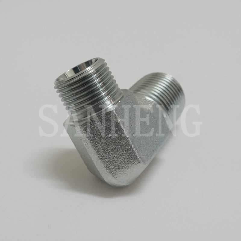
Guessing thread types based on visual similarity leads to stripped threads and dangerous blowouts. Always use a comprehensive fitting types chart alongside physical measurement tools. A digital caliper is required to measure the exact thread outer diameter (OD) and inner diameter (ID). A thread pitch gauge is necessary to determine the number of threads per inch (TPI) or the distance between metric threads. Visually confirm seat angles using a seat angle gauge, and note the exact placement of any O-rings before attempting installation.
National Pipe Tapered threads feature a 1° 47' taper angle. They rely entirely on thread deformation and sealants, such as Teflon tape or liquid thread paste, to prevent leaks. While historically prevalent, hydraulic pipe fittings are actively being phased out of modern high-pressure, high-vibration systems.
The wedging action makes them highly susceptible to cracking female ports if over-tightened. Furthermore, the necessary sealants introduce a high risk of system contamination if applied incorrectly. Pieces of shredded Teflon tape can easily migrate into the fluid stream, jamming sensitive directional control valves or destroying pump internals. Despite these limitations, they remain incredibly common in legacy equipment, pneumatic systems, and low-pressure return lines.
Defined by the SAE J514 standard, JIC fittings utilize a 37-degree machined cone to create a metal-to-metal sealing mechanism. When the nut is tightened, the flared hose end compresses against the male cone.
The primary advantages are wide availability, ease of adaptation, and the ability to withstand high temperatures since there are no rubber O-rings to melt. However, they have distinct cons: they are highly susceptible to "nose collapse" or cracking under over-torque conditions. They also frequently develop weeping leaks in high-vibration applications due to thermal cycling and mechanical loosening. Mechanics often make the mistake of over-tightening a weeping JIC connection, which only further damages the flared seat and guarantees a larger leak.
ORFS is widely recognized as the premium standard for high-pressure, high-vibration environments. Defined by SAE J1453, this design features a captive O-ring seated in a precision-machined groove on the flat face of the male component. As the connection is tightened, the O-ring compresses against the flat face of the female component.
This feature-to-outcome value is massive: it eliminates the risk of over-torquing associated with metal flares, provides zero-clearance assembly (allowing components to be dropped in without pulling hoses back), and delivers a highly reliable, leak-free seal under severe mechanical shock. Heavy equipment manufacturers heavily favor ORFS for excavator boom lines and hydrostatic drive circuits.
O-Ring Boss (ORB) connections are the preferred standard for port connections on pumps, cylinders, and valves. Unlike NPT threads that wedge into the port, ORB utilizes straight parallel threads for holding power and a rubber O-ring at the base of the male thread for sealing.
The O-ring compresses into a specially machined chamfer in the female port. This design allows the component to be fully tightened without risking port expansion or cracking, ensuring a highly reliable seal that can withstand extreme hydraulic pressures. It also allows for adjustable directional fittings, where the mechanic can back off the locknut, point the elbow in the desired direction, and then tighten the nut to compress the seal.
Identifying European and Asian equipment standards requires understanding the nuances of British and German engineering conventions.
BSPP (British Standard Pipe Parallel): Uses parallel threads and seals via a bonded seal (Dowty washer) or an O-ring and retaining ring at the base. It does not seal on the threads.
BSPT (British Standard Pipe Tapered): Similar in function to NPT, it seals via thread interference. However, BSPT has a 55-degree thread angle compared to NPT's 60-degree angle, making them strictly incompatible.
Metric (DIN): German industrial standard fittings use metric threads and a 24-degree cone sealing method. They are divided into the Light Series (DIN L) for standard applications and the Heavy Series (DIN S) for high-pressure environments. The tube outside diameter and thread pitch are essential for accurate identification.
The primary role of hydraulic adapters is bridging mismatched thread types or sizing up and down between components. For instance, an adapter is necessary to connect a metric port on a European hydraulic pump to a standard JIC hose end used in a North American fleet.
While adapters increase system versatility and allow for rapid field modifications, they introduce operational trade-offs. Every adapter adds an additional potential leak point to the circuit. Furthermore, stacking multiple adapters increases the physical length of the connection, altering the moment arm and increasing mechanical stress on the port under vibration. Always advise minimizing adapter stacking by sourcing the correct hose end whenever possible. If you must use an adapter, keep it to a single component rather than building a plumbing tree.
Proper hose routing is a mechanical necessity. Hoses must never be bent beyond their published minimum bend radius. Forcing a tight bend stresses the wire reinforcement, leading to premature fatigue, cover tearing, and eventual rupture.
Utilizing 45-degree and 90-degree hydraulic elbow fittings in tight routing spaces allows the hose to run in a straight line, mitigating mechanical stress. Elbows also prevent hoses from rubbing against sharp chassis components and help eliminate severe pressure drops caused by kinked internal tubing. When installing elbows, always ensure they are oriented correctly before tightening the final connection to prevent twisting the hose assembly.
System architecture often requires specialized directional and structural components.
Tees and Crosses: Used as flow-splitting fittings to distribute fluid from a single pump line to multiple actuators or valve banks.
Unions: Designed to join two hoses together, extending the overall reach of the circuit without replacing the entire hose assembly.
Bulkheads: Engineered to pass fluid safely through structural barriers, such as metal firewalls or machine chassis, providing a rigid mounting point that isolates the hose from sharp metal edges.
Caps and Plugs: Play a critical role in preventing fluid contamination. They must be installed immediately during system maintenance or component storage to block dirt, moisture, and debris from entering precision hydraulic circuits.
QD couplers are essential in systems requiring frequent attachment and detachment, such as agricultural implements, skid steer attachments, and industrial test ports. These components allow operators to connect and disconnect fluid lines rapidly without tools.
Modern push-to-connect mechanisms allow for one-handed operation. High-end flat-face designs are mandatory for environmental compliance and system cleanliness; they utilize flush mating surfaces that minimize fluid spillage during disconnection and prevent air inclusion when the circuit is reconnected. Standard poppet-style couplers are cheaper but prone to trapping dirt in their recessed cavities, which eventually gets pushed into the hydraulic system.
Material selection dictates the lifespan of the connection in its operating environment.
Carbon Steel: The undisputed standard for most industrial and mobile applications. It offers excellent tensile strength, high pressure ratings, and cost-effectiveness. It is typically manufactured from alloys like 12L14 or 1045.
Stainless Steel: Usually machined from 316-grade alloy, stainless steel commands a high initial cost. This cost is justified by its necessity in highly corrosive environments, such as marine applications, offshore drilling, chemical processing plants, and environments subjected to extreme temperature fluctuations.
Brass: Generally restricted to low-pressure applications. Brass is highly compatible with specific fluids, including compressed air, potable water, and certain specialized lubricants. It lacks the tensile strength required for high-pressure hydraulic circuits and will deform under heavy torque.
Bare carbon steel rusts rapidly when exposed to moisture. To combat this, manufacturers utilize modern plating advancements. While traditional hexavalent chromium has been largely phased out due to environmental regulations, modern zinc-nickel plating has become the industry standard.
Zinc-nickel extends the salt-spray resistance of standard carbon steel components significantly, often exceeding 1,000 hours of red rust resistance in standardized testing. This offers a highly effective middle-ground value proposition, providing excellent environmental protection without the extreme cost of solid stainless steel.
Forcing incompatible threads together is a primary cause of catastrophic system failure. Attempting to thread an NPT male into a BSPT female port may feel secure initially due to the similar taper, but the difference in thread pitch (60 degrees vs. 55 degrees) guarantees a spiral leak path and severe thread galling.
Similarly, mating a 37-degree JIC flare with a 45-degree SAE flare will crush the seating surfaces, destroying both components. Advocate strictly for the use of thread pitch gauges and digital calipers during the identification phase to eliminate these severe safety risks and prevent costly equipment damage.
Installation realities dictate that torque accuracy is just as important as component selection. Under-torquing fails to seat the metal cones or compress the O-ring adequately, causing immediate weeping leaks under pressure. Over-torquing is equally destructive; it crushes metal flares, extrudes O-rings out of their grooves, and cracks female ports, leading to delayed catastrophic failure during machine operation.
To mitigate this, recommend the adoption of the Flats From Wrench Resistance (FFWR) method. This process ensures accurate tightening without relying on expensive torque wrenches in dirty field conditions:
Ensure the threads and sealing surfaces are clean and free of damage.
Thread the nut on by hand until it bottoms out against the mating surface.
Mark a line across one flat of the hex nut and extend it onto the fixed component.
Use a wrench to turn the nut a specific number of hex flats (e.g., 1.5 to 2 flats for a -8 JIC fitting) as dictated by the manufacturer's chart.
Hydraulic connections are not install-and-forget components. Establish rigorous protocols for routine inspection. Technicians must actively identify weeping joints, which often indicate vibration-induced loosening or thermal degradation of the seal.
Check for hoses that have twisted during operation, as this places severe rotational stress on the crimp shell. Most importantly, schedule the replacement of elastomeric seals (O-rings) before they degrade, harden, and cause system failure. A proactive maintenance schedule prevents minor leaks from escalating into hazardous blowouts and expensive environmental cleanup.
Audit your current equipment fleet to identify the dominant thread standards and standardize replacement parts to minimize inventory overlap.
Equip all maintenance vehicles with digital calipers, thread pitch gauges, and seat angle gauges to eliminate visual identification errors in the field.
Transition legacy NPT connections to ORFS or ORB standards during major system overhauls to improve vibration resistance and eliminate thread sealants.
Implement the Flats From Wrench Resistance (FFWR) method across your technician team to standardize installation torque and prevent crushed flares.
A: No. Teflon tape or liquid thread sealants should only be used on tapered threads like NPT or BSPT. Applying sealant to JIC flares, ORFS, or ORB connections interferes with the mechanical or elastomeric seal, introduces contamination into the hydraulic fluid, and causes severe leaks.
A: JIC fittings feature a 37-degree flare angle, while SAE flare fittings use a 45-degree angle. You must use a seat angle gauge to measure them accurately. Mixing the two will crush the seating surfaces and result in immediate failure.
A: ORFS leaks typically result from a missing O-ring, a pinched or extruded O-ring due to over-torquing, or elastomer degradation from fluid incompatibility or excessive heat. Inspect the flat face for deep scratches and replace the O-ring with the correct material grade.
A: The dash system measures the size of hoses and components in 1/16th of an inch increments. For example, a -8 (dash eight) fitting corresponds to 8/16, which simplifies to a 1/2-inch size. It ensures standardized sizing across different thread types.
A: Field-attachable (reusable) fittings are generally not recommended for continuous high-pressure, high-vibration applications. They are best suited for lower-pressure return lines or temporary emergency repairs. Permanent crimped assemblies are required for maximum safety and reliability.
A: Never rely on "feel." You must use a calibrated torque wrench and follow the manufacturer's specific torque chart for that exact thread type and size. Alternatively, use the Flats From Wrench Resistance (FFWR) method to ensure proper seating without crushing the component.


