
Views: 0 Author: Site Editor Publish Time: 2026-08-17 Origin: Site


Mismatched pressure ratings in fluid power systems cause severe operational failures. These mismatches lead to catastrophic blowouts, hazardous fluid injection injuries, and unplanned downtime. Engineers and procurement teams frequently struggle to align dynamic system pressures with the correct fitting materials, thread types, and attachment methods. Relying solely on static pressure ratings often leads to failures under real-world surge conditions. Prioritizing ease of installation over pressure integrity introduces massive safety risks.
Selecting reliable hydraulic hose fittings requires a rigorous evaluation of working pressure and burst pressure safety factors. You must also evaluate material strength and specific connection styles. This technical framework provides the exact methodology required to specify fittings for high-stakes, high-pressure environments. You will learn how to match component limits with dynamic system demands effectively.
The maximum working pressure of a hydraulic assembly is strictly dictated by its weakest component; a high-pressure hose paired with a low-pressure fitting reduces the entire system’s rating to the fitting’s limit.
Dynamic pressure spikes (surges) require a standard 4:1 safety factor (burst pressure to working pressure) to prevent structural failure.
Fitting size inversely affects pressure capacity: as the nominal diameter (dash size) increases, the maximum allowable working pressure generally decreases.
Thread and seal designs dictate high-pressure viability: ORFS hydraulic hose fittings offer superior leak resistance in high-vibration, high-pressure applications compared to traditional metal-to-metal flares.
Permanent attachment methods, specifically swaged hydraulic hose fittings, are mandatory for high-pressure reliability, rendering reusable fittings obsolete for heavy-duty applications.
Understanding pressure terminology dictates the safety of fluid power design. Maximum Allowable Working Pressure (MAWP) defines the absolute highest pressure a component can sustain during continuous operation. You calculate MAWP based on material yield strength and physical wall thickness. The fitting's MAWP must always exceed the system's maximum relief valve setting. If the relief valve triggers at 4,000 PSI, every component in that circuit must have a MAWP greater than 4,000 PSI. Failing to maintain this margin guarantees premature component fatigue.
Static pressure represents a constant, unchanging load within a system. Dynamic pressure involves rapid fluctuations, surges, and spikes. When directional control valves open or close rapidly, they create a water hammer effect. The moving column of hydraulic fluid stops instantly, converting kinetic energy into pressure energy. This creates a shockwave that travels back through the lines at the speed of sound in oil. A system running at 3,000 PSI statically might experience 4,500 PSI dynamic surges during cylinder bottoming. You must specify components based on these dynamic spikes, not just the steady-state operating pressure.
Testing metrics validate component safety before field deployment. Proof Pressure verifies assembly integrity without causing permanent deformation. Manufacturers typically test Proof Pressure at 200% (a 2:1 ratio) of the intended working pressure. Burst Pressure represents the exact point of catastrophic structural failure. Fluid power standards mandate a strict 4:1 safety factor for dynamic systems. This rule requires the burst pressure to be exactly four times the maximum working pressure. If a fitting has a MAWP of 5,000 PSI, its engineered burst pressure must be at least 20,000 PSI.
The weakest link principle governs all fluid power assemblies. An assembly consists of the hose, the hose ends, and the adapters. The overall pressure rating of this complete assembly equals the rating of its lowest-rated component. Connecting a 6,000 PSI rated hose to a 3,000 PSI rated fitting creates a 3,000 PSI assembly. You cannot average the ratings or rely on the hose's superior wire reinforcement to compensate for a weak connection.
Pressure Metric | Definition | Industry Standard Ratio | Field Application |
|---|---|---|---|
Maximum Allowable Working Pressure (MAWP) | Highest continuous operating pressure | 1:1 (Baseline) | Must exceed system relief valve setting |
Proof Pressure | Test pressure to verify no deformation | 2:1 (200% of MAWP) | Factory quality control testing |
Burst Pressure | Point of catastrophic structural failure | 4:1 (400% of MAWP) | Safety margin for dynamic shock loads |
Dynamic Surge Pressure | Momentary pressure spikes from valve actuation | Variable (Often 150% of MAWP) | Dictates the need for high-fatigue materials |
Material selection directly dictates the maximum pressure threshold of any fluid power connection. Stainless steel stands as the premium choice for ultra-high-pressure applications. Systems operating above 10,000 PSI almost exclusively require stainless steel components. It offers exceptional tensile strength and resists deformation under extreme mechanical stress. Stainless steel also withstands highly corrosive environments, preventing rust from compromising the fitting's structural integrity. Offshore drilling rigs and chemical processing plants rely on 316 stainless steel to prevent catastrophic blowouts.
Carbon steel serves as the industry standard for medium-to-high pressure industrial and mobile hydraulics. It provides excellent mechanical strength. However, raw carbon steel corrodes rapidly when exposed to moisture. You must specify carbon steel components with advanced protective plating. Zinc-nickel plating is the current standard, offering superior resistance to red rust. If the plating degrades, oxidation will eat into the metal. This corrosion reduces the wall thickness and severely compromises the pressure holding capacity over time.
Brass carries strict structural limitations in fluid power systems. It is a relatively soft metal with low tensile strength. You should only specify brass for low-pressure applications, typically those operating well under 3,000 PSI. The exact limit depends heavily on the component's physical size. Brass works well for specific fluid compatibilities, such as pneumatic lines or low-pressure return lines. Never use brass in heavy dynamic hydraulic systems experiencing high-pressure surges. The soft metal will deform, strip its threads, and fail catastrophically under surge conditions.
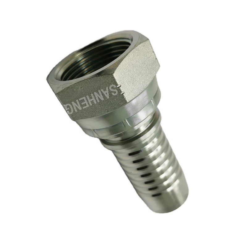
O-Ring Face Seal connections utilize an elastomeric seal to contain fluid. The seal sits in a machined groove on the face of the male fitting. When tightened against a flat female mating surface, the O-ring compresses. This compression creates a leak-free, zero-clearance connection. The metal surfaces touch, preventing the O-ring from extruding under pressure.
Engineers specify ORFS hydraulic hose fittings as the optimal choice for high-pressure and high-vibration environments. They reliably handle continuous operating pressures up to 6,000 PSI. The elastomeric seal absorbs micro-vibrations that would otherwise loosen threaded metal connections. You must match the O-ring material to the system's fluid type and operating temperature. Nitrile works for standard hydraulic oil, while Viton handles high-heat synthetic fluids. This matching yields the highest possible reliability against weeping and fluid loss.
The Joint Industry Council (JIC) standard relies on a metal-to-metal sealing mechanism. The male fitting features a 37-degree flared seating surface. The female fitting has a matching machined flare. As you tighten the nut, the two angled metal surfaces wedge together. This mechanical wedging action creates the fluid seal without any rubber components.
You can evaluate JIC hydraulic hose fittings for medium-to-high pressure applications. They are universally available and highly standardized. However, they carry specific implementation risks. JIC connections are susceptible to weeping under extreme high pressure or heavy vibration. The metal-to-metal seal can suffer from metal fatigue over time. Furthermore, over-torquing during installation easily cracks the flare, destroying the pressure integrity entirely.
Flange connections solve the installation challenges of large diameter hoses. Threading a massive two-inch fitting requires immense torque and physical clearance. Flanges use split metal halves, four bolts, and a captive O-ring. You bolt the split halves onto a flat port face, compressing the O-ring to form the seal. This design allows for easy installation in tight spaces.
Pressure suitability depends entirely on the flange code. Code 61 flanges handle standard pressures, ranging from 3,000 to 5,000 PSI depending on the nominal size. As the Code 61 flange gets larger, its pressure rating drops. Code 62 flanges are engineered for heavy-duty applications. They maintain a consistent 6,000 PSI rating across all physical sizes. You must specify Code 62 for any large-diameter, high-pressure dynamic circuit.
Quick disconnect couplers serve operational needs requiring frequent maintenance. They allow operators to connect and disconnect lines rapidly without wrenches. This modularity is necessary for changing attachments on mobile equipment like skid steers and excavators. However, standard push-to-connect QDs have significantly lower pressure thresholds than solid threaded connections.
High-pressure scenarios demand specialized threaded flat-face couplers. Standard ball-bearing QDs can blow apart under severe pressure spikes because the locking balls brinell into the metal under shock loads. Threaded QDs lock the halves together mechanically, preventing blowout and dangerous fluid injection hazards. Even with heavy-duty QDs, a permanent threaded connection will always provide superior pressure integrity and safety.
Connection Type | Sealing Mechanism | Max Pressure Capability | Vibration Resistance |
|---|---|---|---|
ORFS (O-Ring Face Seal) | Elastomeric O-Ring Compression | Up to 6,000 PSI | Excellent |
JIC (37-Degree Flare) | Metal-to-Metal Wedge | Up to 5,000 PSI (Size Dependent) | Moderate (Prone to weeping) |
Code 62 Flange | Captive O-Ring & Bolted Split Halves | 6,000 PSI (All Sizes) | Very Good |
Threaded Flat-Face QD | Mechanical Thread Lock & Internal Seals | Up to 5,000 PSI | Good |
Permanent attachment relies on a precise cold-forming process. A hydraulic press compresses the metal collar of the fitting around the hose exterior. This swaging or crimping process physically bites into the internal steel wire reinforcement of the hose. The compression creates a unified, inseparable assembly. The metal flows into the rubber, locking the components together permanently.
For any high-pressure application, permanent swaged hydraulic hose fittings are strictly non-negotiable. They provide the structural integrity required to withstand dynamic pressure spikes. Using permanent connections ensures safety compliance and drastically reduces corporate liability. You must adhere to exact crimp specifications provided by the manufacturer. Using a digital micrometer to verify the final crimp diameter ensures the assembly achieves its maximum pressure holding capability.
Achieving maximum pressure holding capacity requires proper hose preparation before swaging. No-skive hoses allow you to crimp the fitting directly over the outer rubber cover. The fitting's internal teeth bite through the rubber to grip the wire braid. This method is fast and protects the wire from moisture. However, for ultra-high-pressure multi-spiral hoses, you must use a skiving process. Skiving involves stripping away the outer rubber cover to expose the bare steel wire. The swaged fitting then clamps directly onto the steel reinforcement. This metal-to-metal grip provides the absolute highest blowout resistance for extreme dynamic pressures.
Field attachable fittings thread onto the hose manually using standard hand tools. You thread the outer socket counter-clockwise onto the hose, then drive the tapered inner stem clockwise into the tube. This action wedges the hose against the outer socket. While convenient, these connections lack the deep mechanical bite of a swaged connection.
You must strictly limit reusable fittings to low-pressure applications. They are sometimes acceptable for temporary emergency repairs in the field to move a machine to a maintenance bay. Using reusable connections in dynamic, high-pressure circuits introduces severe blowout risks. The mechanical wedge can loosen under vibration and pressure surges, leading to catastrophic failure and extreme liability.
The STAMPED framework (Size, Temperature, Application, Material, Pressure, Ends, Delivery) guides component selection. Size directly dictates pressure limits. There is an inverse relationship between component diameter and pressure rating. A -4 (1/4 inch) fitting can safely handle significantly higher pressures than a -16 (1 inch) fitting of the exact same material and style. As the internal surface area increases, the total outward force exerted by the fluid increases exponentially.
Temperature requires you to derate the pressure capacity. Elevated ambient or fluid temperatures reduce the effective pressure rating of all materials. Heat softens sealing elastomers, causing them to extrude out of their grooves under high pressure. Heat also reduces the tensile strength of metals, especially brass and standard carbon steel. You must consult manufacturer derating charts if your system operates above 200°F (93°C).
Application and Material must align with the pressure demands. Map specific high-pressure applications to required materials. Hydrostatic drives, heavy lifting equipment, and hydraulic presses generate massive dynamic surges. These applications demand stainless steel or heavily plated carbon steel. They also require vibration-resistant ends like ORFS or Code 62 flanges. Never specify low-tier materials for high-impact applications.
Pressure dictates the relief valve setting plus the surge factor. Ends dictate the thread geometry required to hold that pressure. Delivery dictates the volume and velocity of fluid, which creates turbulence and heat, indirectly affecting the pressure holding capability of the entire assembly over time.
Mixing manufacturers introduces severe structural risks. You must never combine hoses from Brand A with ends from Brand B. Mismatched machining tolerances lead to improper compression during the crimping process. The fitting may look secure but will suffer catastrophic blowout under high pressure. Mixing brands immediately voids manufacturer warranties and invalidates safety certifications.
Torque specifications determine the survival of threaded connections. Over-torquing is a massive risk, especially on JIC metal-to-metal flares. Excessive force crushes the 37-degree cone, causing immediate leaks. Under-torquing allows the connection to vibrate loose during pressure spikes. You should use the Flats From Wrench Resistance (FFWR) method to ensure accurate installation.
Inspect the threads and sealing surfaces for damage or contamination.
Lubricate the threads with clean hydraulic fluid to prevent galling.
Thread the nut by hand until it bottoms out on the mating surface.
Use a wrench to tighten until you feel solid metal-to-metal resistance.
Mark a line across the nut and the fitting body.
Turn the nut with a wrench the specified number of hex flats based on the manufacturer's size chart.
Routing and mechanical stress destroy fittings prematurely. Improper hose routing introduces side-load stress onto the metal threads. If you bend a hose too tightly right next to the crimp shell, the pressure will pry the fitting apart over time. You must respect the minimum bend radius. Furthermore, balance the need for secure high-pressure connections with physical accessibility. Technicians need adequate wrench clearance to apply the correct torque safely.
Audit your current fluid power schematics to identify all maximum relief valve settings and potential dynamic surge zones.
Cross-reference existing assembly specifications against manufacturer pressure-temperature derating charts to verify safety margins.
Implement a mandatory digital micrometer check for all crimp diameters before installing new assemblies on the equipment.
Transition high-vibration circuits from metal-to-metal flares to elastomeric face seals to eliminate weeping leaks.
A: Working pressure (MAWP) is the maximum continuous pressure a component can safely handle. Proof pressure is a testing metric, usually double the working pressure, verifying the component won't deform. Burst pressure is the exact point of catastrophic structural failure, required to be four times the working pressure in dynamic systems.
A: The overall assembly rating drops to match the lowest-rated component. If you put a 3,000 PSI fitting on a 6,000 PSI hose, the maximum safe operating pressure for that entire line becomes 3,000 PSI. Exceeding this limit will cause the fitting to fail.
A: JIC fittings are not ideal for high-vibration environments. Their metal-to-metal 37-degree flare seal is susceptible to micro-movements. Heavy vibration can loosen the connection or cause metal fatigue, leading to weeping leaks. O-Ring Face Seal (ORFS) connections are much better suited for high vibration.
A: Pressure is force divided by area. As the internal diameter of a fitting increases, the surface area exposed to the fluid increases. This larger area multiplies the total outward force pushing against the metal walls, reducing the maximum pressure the component can safely contain.
A: No. Reusable (field attachable) fittings lack the deep structural bite of permanent swaged connections. They are strictly limited to low-pressure applications or temporary emergency repairs. High-pressure dynamic systems require permanent crimped connections to prevent blowout hazards.
A: Elevated temperatures reduce the tensile strength of metals and soften elastomeric seals. This thermal degradation lowers the component's ability to hold pressure. You must apply a derating factor to the maximum working pressure if the system operates above standard temperature thresholds.


